
We have written this to make it easy for anyone to understand & test trailer lights. Feel free to print this page & wiring diagrams to take them out in the shop or driveway to help you find & fix the problem. There are full page plug and receptacle diagrams located at the end of this document. Step 1 is to find out if the problem is in the tow vehicle electrical system, or if the problem is in the trailer wiring. We will show you how to check both.
GROUNDING
Before you dive into testing & fixing trailer lights, understand how important grounding is to trailer lighting. It doesn’t matter whether your trailer has LED (Light Emitting Diode) lighting or filament bulbs, they both need a good ground to illuminate. A light fixture may use the metal part of the frame to serve as the ground, or a more common (& better) way is to run a separate ground wire to each fixture on a trailer. This ground originates at the towing vehicle battery’s negative terminal & must travel back through the truck to trailer plug, then to each trailer light fixture. A bad or missing trailer ground is a VERY COMMON reason that lights don’t work on a trailer, or they only work sometimes. If you have ever followed a truck/trailer at night & you see the lights flickering, that is probably a bad ground between the truck & trailer. Never rely on the metal to metal contact between the tow ball on a truck & the hitch on a trailer to serve as the ground connection between the two. A pin on the truck socket & a pin on the trailer plug are dedicated for this ground connection, so test that connection 1st when troubleshooting a problem.
Wiring Colors – Be Careful!
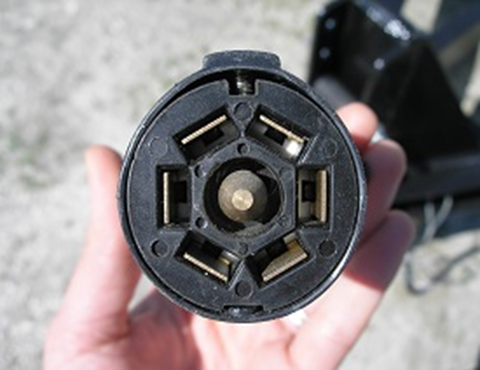
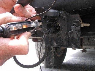
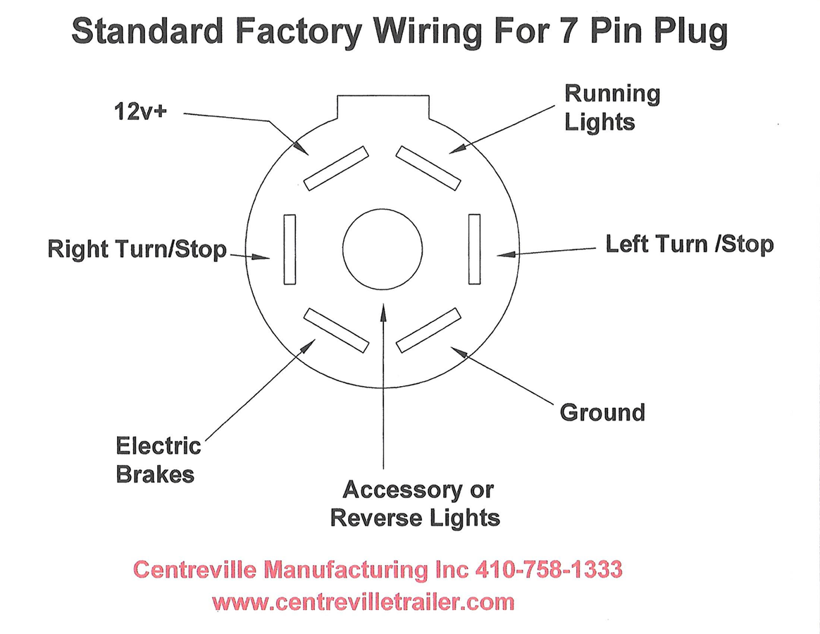
We encourage you to ignore the wiring color codes that are shown on trailer plugs. There is a wide variety of colors used by trailer manufacturers, truck manufacturers, RV manufacturers, not to mention a variety of mechanics & previous owners that may have worked on your truck or trailer before. We want you to focus on the pin location & function on a trailer plug, rather than the color of the wire connected to it. Basically, assume the wiring colors are wrong when troubleshooting; then you can be pleased if they turned out to be right. Also be mindful of the orientation of the plug when matching each pin to its function. The recessed rectangular area at the top of the receptacle is a helpful way to assist in determining the orientation.
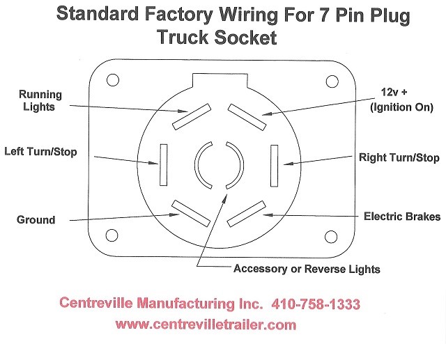
This photo above shows the orientation of the receptacle rotated clockwise 90°. Note that the recessed rectangle is located on the right hand side. (Note that the recessed rectangle is at the top of the diagram. Use this as a reference point when determining which pin is for which function.)
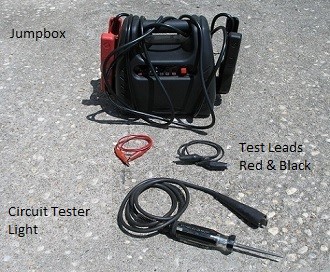
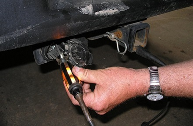
Pictured above is all that you will need to test the wiring on your towing vehicle & trailer. We will show you 2 different ways to test the wiring on your towing vehicle.
.
.
TESTING THE TRUCK / VEHICLE
Tools Required: Use the Circuit Light Tester & Alligator Clip Test Leads.
Helpful Documents: It would be helpful to print out the wiring diagram for the vehicle end receptacle to look at while you are testing to assure that you are testing the correct pin.
Assistant (Recommended): You will need someone in the vehicle to help you with this portion of the test.
Step by Step Instructions
- Wire, tape, or prop the spring loaded door of the receptacle open to keep it out of your way.
- Connect the test light to one end of a test lead.
- Connect the opposite end of that test lead to the “Ground” pin on the receptacle. (Make sure that it is making good contact to the metal on the pin.)
- Have an assistant turn the key of the vehicle ON and leave it turned on for the remaining tests.
- Touch the test light to the “Running Lights”.
- Have an assistant turn on the vehicle’s lights. (This should cause your test light to illuminate).
- Touch the test light to the “Right Turn/Stop” pin.
- Have an assistant turn on the right hand turn signal. (The test light should illuminate, blinking as the turn signal would).
- Have an assistant also press the brake pedal. This should cause your test light to illuminate.
- Touch the test light to the “Left Turn/Stop” pin.
- Have an assistant remove foot from brake & turn on the left hand turn signal. The test light should illuminate, blinking as the turn signal would.
- Touch the test light to the “12V+” pin. Your test light should illuminate, proving that you are receiving voltage from the vehicle battery & that your ground pin is good.
- Have an assistant also press the brake pedal again. This should cause your test light to illuminate.
- Touch the test light to the “Accessory or Reverse Lights” pin.
- Have an assistant put the emergency brake on & firmly press the brake pedal & put the vehicle into reverse. (Note: Highly Dangerous, perform this step with great care!) This should cause your test light to illuminate. If you have an accessory wired to this pin, turn it on & your test light should illuminate.
.
.
Optional: If Your Trailer has Electric Brakes
- Touch the test light to the “Electric Brakes” pin. This only applies if your vehicle is equipped with an electric brake controller.
- Have your assistant slowly squeeze the hand operated slide for the electric brake controller.
- The test light should start out dim and get brighter as the outgoing power from the brake controller increases.
- Some brake controllers have a test feature, which will cause the test light to blink.
.jpg)
.jpg)
Test Failures – Light Did Not Light
If your circuit tester did not illuminate for any of the functions, it is likely that you have a bad ground. You can test this by removing the test lead from the ground pin on the plug & grounding it directly to the vehicle. Make sure that you are making contact with bare metal.
Retry all of the tests to see if the circuit tester now illuminates, this proves a bad ground pin. This could be cause by the adapter on the truck or the wiring to the adapter, both should be thoroughly checked.
TESTING THE TRUCK
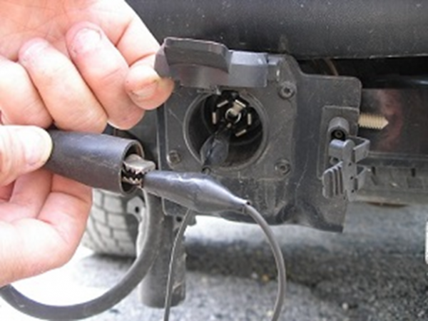
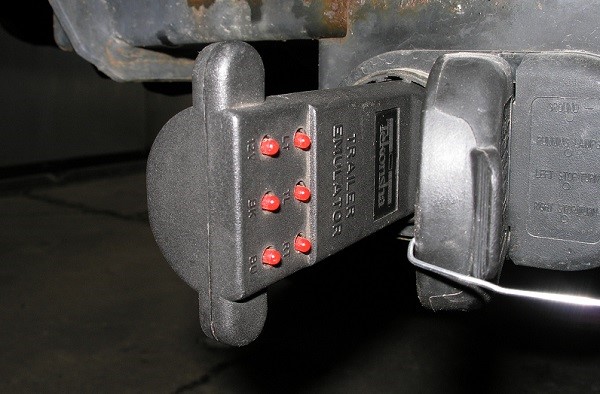
Tools Required: Use a Truck Trailer Plug Tester with LED Display. This tester plugs into the receptacle and has an LED light indicator for each of the pins.
Assistant (Recommended): You will need someone in the vehicle to help you with this portion of the test.
- Plug the tester into the truck’s receptacle.
- Have an assistant complete each of the functions: turn on vehicle (12v), turn on vehicle’s lights (TL – trailer/running lights), turn on left turn signal (LT – Left Turn), turn on right turn signal (RT – Right Turn), apply brakes (LT & RT), squeeze electric brake controller slide (BK – Electric Brakes), put vehicle into reverse/turn on accessory (BU – Backup/reverse or accessory).
- The corresponding LED light on the tester should illuminate for each of the applicable functions. The LT & RT lights should blink when the left & right turn signals are turned on. The BK light should brighten as you increase the outgoing power from the electric brake controller. It may also blink if your brake controller has a test function.
If the ground pin on the vehicle receptacle is not working, none of lights will illuminate.
TESTING THE TRAILER
Tools Required: Battery or Jump Box & Alligator Clip Test Leads.
Assistant (Recommended): You will need an assistant to view & assist the trailer while performing portions of the test.
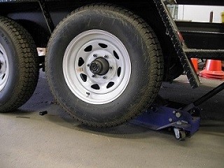
Electric Brakes: If your trailer is equipped with electric brakes you will need a floor jack that enables you to jack up one wheel at a time.
It is important to remember that the pins for the trailer plug will not correspond to the same functions as they do on the vehicle end receptacle diagram. Since they are plugging into each other, the plug & receptacle diagrams are a mirror image.
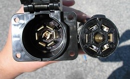
Remember to match the orientation of the plug to the diagram. When holding the plug, the rectangular “bump” should be at the top.

Note that the rectangular “bump” is located at the top of when looking directly at the face of the plug.
Step by Step
- Using a battery or jump box, connect one end of the black test lead to the negative terminal & the other end to the “Ground” pin. It is helpful to use corresponding colors for the test leads, as shown. Black for the negative terminal & red for the positive.
- Connect the second test lead to the positive terminal of the battery or jump box. Now we will begin to the test the functions on the trailer by touching the opposite end of the second (red) test lead to each of the pins.
- Make contact with the alligator clip to the “Left Turn/Stop” pin.
- The left turn signal/stop light should come on when you energize the circuit.
- Touch the alligator clip to the “Running Lights” pin.
- When you energize the circuit, the trailer’s running lights should come on.
- Make contact with the test lead to the “12v+” pin.
- If you have a trailer that is equipped with electric brakes & a breakaway battery that has a “charging” indicator light, it should illuminate when you energize the circuit.
- Touch the alligator clip to the “Right Turn/Stop” pin.
- The right turn signal/stop light should come on when the circuit is energized.
- Make contact with the “Accessory or Reverse Lights” pin.
- If your trailer is equipped with reverse lights, the backup lights should illuminate when you energize the circuit.
- If you wired an accessory up to this pin, that accessory should turn on when the circuit is energized.
.
.
Trailers with Electric Brakes
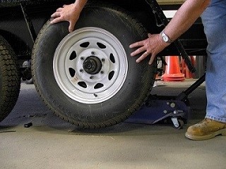
- For the “Electric Brakes” function, you will need to jack the trailer up one wheel at a time.
- Have an assistant spin the wheel in the direction it would spin when traveling forward on the road.
- Connect the alligator clip to the “Electric Brakes” pin.
If the “Ground” pin on the trailer is not working, none of the functions will work. It is common to overlook the ground when problem solving. It is important to test it first!
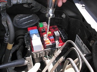
If you pinpointed an issue on your towing vehicle, be sure to check your fuses first. You can use your circuit tester light to do this as well (see below). Look in your vehicle’s owner manual to see which fuses are for which functions.
Hopefully, this helped you to identify the problem in your truck or trailer wiring system. Once you have narrowed down the issue, the next step is fixing it!
Did you determine that your vehicle receptacle or trailer plug needs to be replaced? Check out our large selection of trailer plugs & trailer receptacles!
Click here to view all of our Electrical parts!
Click here to view all of our Lighting & Light Kits!